Spooler Lite
The guide is free to read. You pay for access to the production files (STL, DXF, STEP, PDF, ZIP) and the assembly videos.
- €79Sign in to buy
Spooler Lite
Spooler Lite
Build guide
Spooler Lite
A mechanical unwinder without display and electronics: body, rollers and a pass-through head.
- Body, rollers and a pass-through head
- STL models and the files of the guide
- Step-by-step guide, bill of materials and videos
- Files
- Bill of materials · 11
- Updated 31 Oct 2026
🔒 Production files and videos
The guide is free to read. You pay for access to the production files (STL, DXF, STEP, PDF, ZIP) and the assembly videos.
- €79Sign in to buy
Spooler Lite
Spooler Lite
Downloads
Assembly guide (PDF)
printable guide, all chapters
All files (ZIP)
guide, 3D models, files and videos
3D models Spooler Lite (STL)
12 parts: body, rollers, pass-through head (the spool parts are in the spool guide)
Bill of materials
The list covers the shared parts (rollers, body). The Spooler Lite head has different parts, its list is not available yet.
| Qty | Item | Category | Note |
|---|---|---|---|
| 4 | Screw M4x10 | Screws | Latch 2, catch 2 |
| 8 | Screw M5x16, countersunk head | Screws | Packout holders |
| 2 | Screw M5x20 | Screws | Bases |
| 3 | Screw M5x50 | Screws | Joins the arms |
| 8 | Screw M8x20 | Screws | 4 axes, 2 screws per axis |
| 16 | Washers 8x12 and 8x16 | Screws | 8 + 8, each end of 4 axes |
| 4 | Insert M4 | Inserts | Latch and catch |
| 9+ | Insert M5 | Inserts | |
| 8 | Bearing 608-2RS | Mechanics | 4 axes, 2 bearings per axis |
| 4 | Axis M8 aluminium, 71 mm | Mechanics | Roller, lathe |
| 1 | Draw latch K2469 + catch K2468 | Mechanics | Kipp |
GuideSpooler Lite
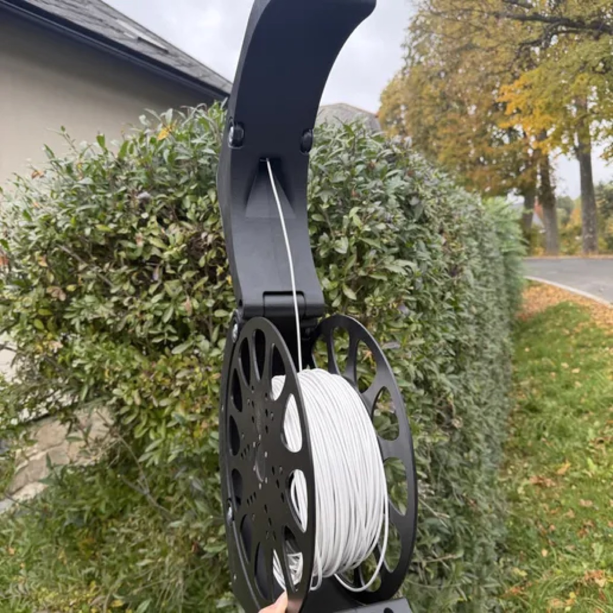
Spooler measures and dispenses cable and suits electricians in the field. Spooler Lite has no display and no sensor, the cable simply unwinds from the spool. You print most of the parts; the rest are turned and laser-cut parts, threaded inserts and bought components such as screws and washers. You can buy the turned and laser-cut parts in the e-shop.
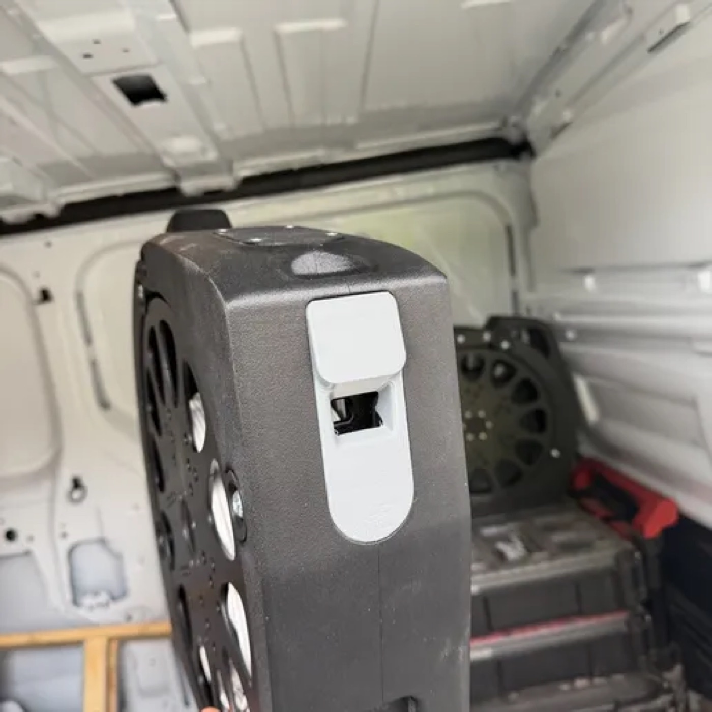
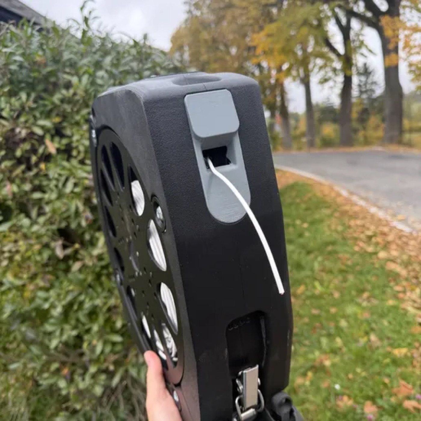
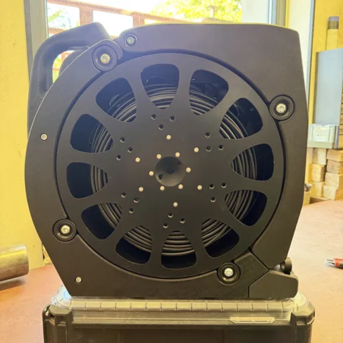
Here is an overview of the parts you need to make. Almost all of them are printed; the rollers and the axis are turned. For smaller printers the model is split with dovetail joints and is made for a 256x256 mm print bed. You can print in ASA-CF or in material of the Spectrum brand.
The parts of the spool are in the spool guide.
All STL models (ZIP) (2.9 MB) ·
Body
| Part | Made by | Note |
|---|---|---|
| 02-01-030d-BASE-LEFT | 3D print | |
| 02-01-031d-BASE-RIGHT | 3D print | |
| arm left | 3D print | left arm, Spooler Lite |
| arm right | 3D print | right arm, Spooler Lite |
| 02-01-035d-BASE-FRONT | 3D print | |
| 02-01-040-Milwaukee_Packout | 3D print | Packout holder |
| 02-01-041-RYGL-L | 3D print | |
| 02-01-061-CLIP_BASE-M4-assy | 3D print | latch base |
Encoder head
| Part | Made by | Note |
|---|---|---|
| 02-00-205-ENCODER-base without electronic | 3D print | base the cable passes through |
| Spring holder cap | 3D print | head cap |
Rollers
| Part | Made by | Note |
|---|---|---|
| 02-01-020a-ROLL | lathe | nylon, or printed |
| 02-01-021-AXIS M8x15 | lathe | axis, aluminium |
Threaded inserts
Most joints use plastic threaded inserts (M3, M4, M5, M6). Press them in before you screw the parts together, always into the part named in the drawing next to the insert. The numbers are given with each assembly in its guide. The inserts are heat-set with a soldering iron with a flat tip: place the insert on the hole, press it slowly into the part with the heated tip until it is flush, and let it cool before you load the part.
Next you build the head, the rollers and the body. What to buy and where is in the last chapter.
Step 1Spooler Lite head
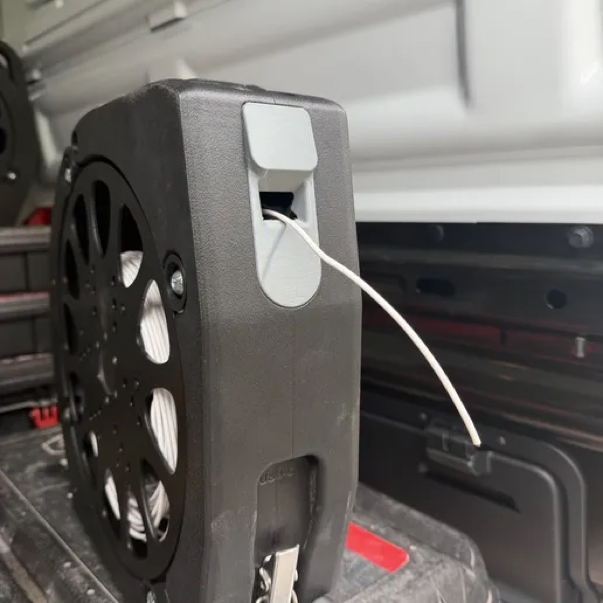
Spooler Lite has no measuring head, only a simple pass-through head. The cable is pulled out of the spool through the opening in the head. It measures nothing, so there is no display, no AS5600 sensor, no button, no wheel with a magnet and no pusher. The spool (it has a guide of its own), the rollers and the body are the same in both versions, only the base of the head differs.
The head is made of two printed parts: a base and a cap. The cap probably covers a hole in the base.
The parts that are different
| Part | Folder | Note |
|---|---|---|
02-00-205-ENCODER-base without electronic | Encoder base | The base of the head that the cable passes through. No room for the display and the AS5600 board |
Spring holder cap | Encoder base | The cap that probably covers a hole in the base |
Step 2Rollers
The rollers carry the spool: the spool sides sit in them and the spool turns on them. They are the same in both versions of the device. There are eight in every device. One assembly is made of an aluminium axis, two 608 bearings and two rollers, so the device needs four assemblies, that is four axes. The axis is turned, 71 mm long, with an M8 thread 15 mm long at both ends.
What you will need
| Qty | Part | Note |
|---|---|---|
| 2 (8 in all) | 02-01-020a-ROLL | Roller. Turned from nylon, printed, or from the e-shop |
| 1 (4 in all) | 02-01-021-AXIS M8x15 | Aluminium, 71 mm, M8 x 15 thread at both ends |
| 2 (8 in all) | Bearing ZKL 608-2RS | |
| 2 (8 in all) | Washer 8x12 | As in the drawing, on each side |
| 2 (8 in all) | Washer 8x16 | |
| 2 (8 in all) | Screw M8x20 |

Assembly
1. Fit the washers and bearings
On each end of the axis put a washer 8x12 and a washer 8x16, then a bearing 608-2RS.
2. Fit the rollers
Put a roller ROLL on each bearing. The roller must turn freely on the bearing.
3. Secure with the screws
Secure the assembly from both sides with an M8x20 screw into the thread at the end of the axis.
Putting it into the body
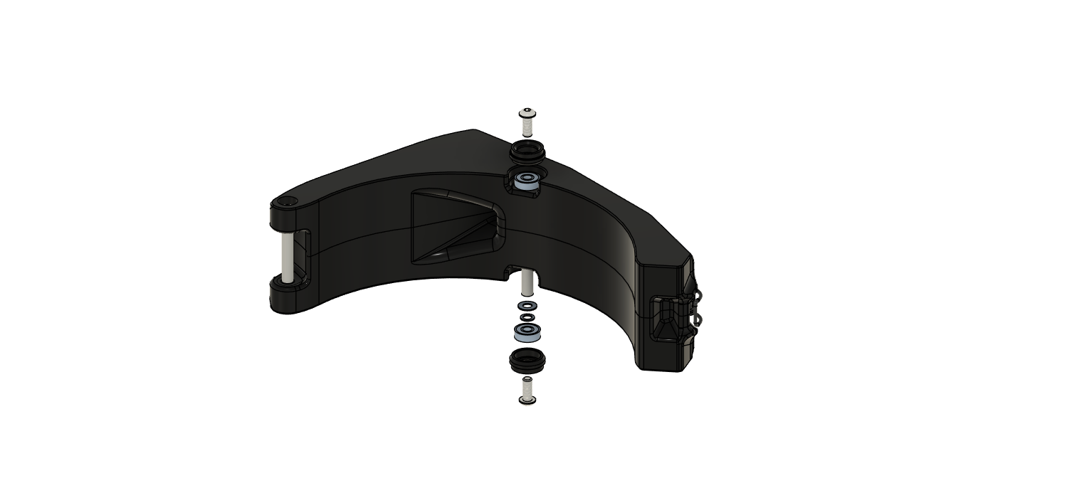
4. Put the assembly into the arm
Put the finished assembly into the arm as in the picture. Check that both rollers turn freely.
Step 3Body
The body is made of two arms with a base, a front part and holders. Spooler Lite has no battery holder, no board and no wiring, the arms are simply joined.
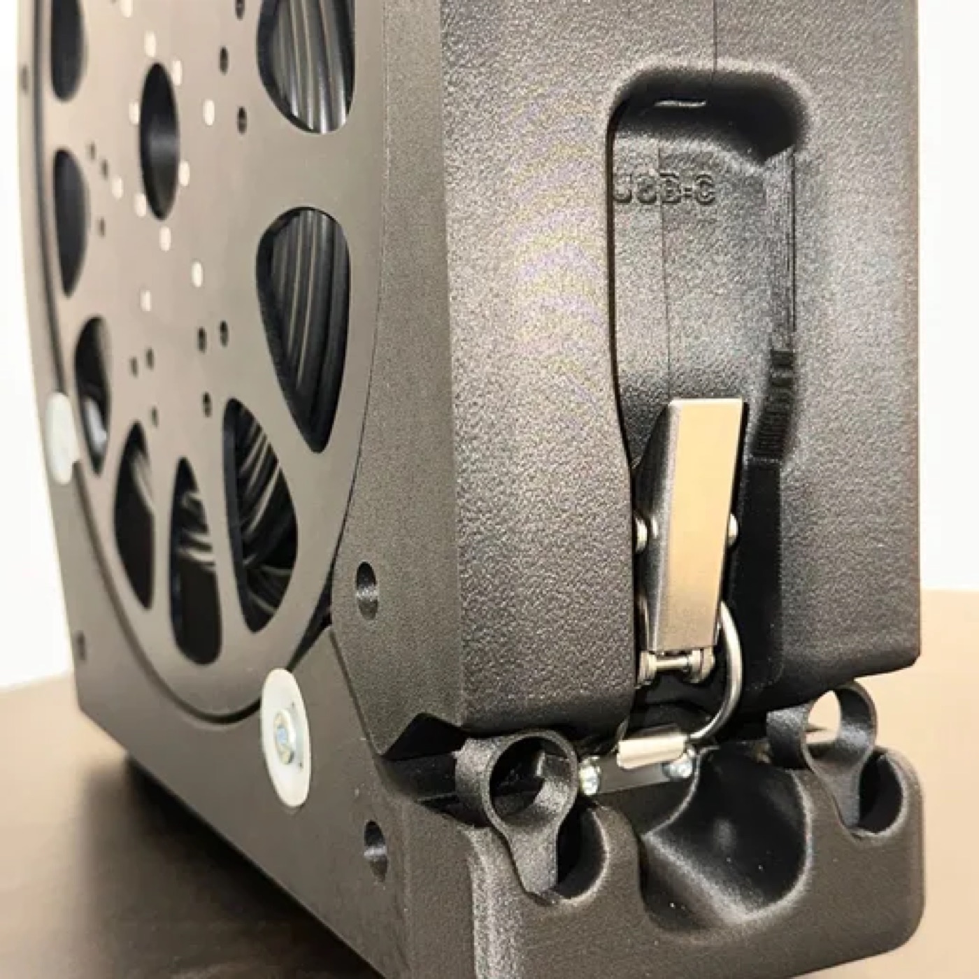
1. Fit the latch
Press in two M4 inserts. Put 02-01-061-CLIP_BASE-M4-assy and the latch K2469 in place and screw them on with two M4x10 screws.
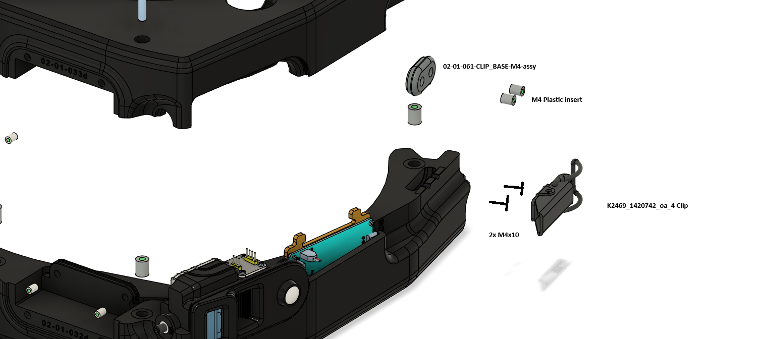
2. Join the arms
Press M5 inserts into the arms arm left and arm right. Put the arms together and pull them tight with three M5x50 screws. The arms have the same dimensions as 02-01-032d-ARM-LEFT and 02-01-033d-ARM-RIGHT of the Spooler Smart and differ only in small details.
3. Fit the front part
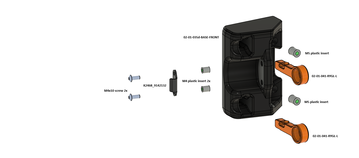
Press two M5 inserts for 02-01-041-RYGL-L (2 pcs) and two M4 inserts for the latch catch K2468 into 02-01-035d-BASE-FRONT. Screw the catch on with two M4x10 screws.
4. Screw on the bases and the Packout holders
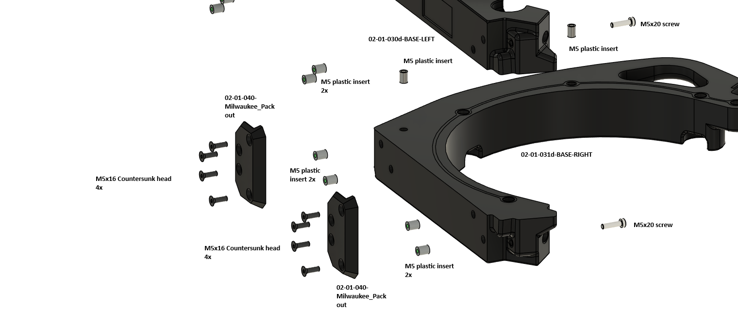
Press M5 inserts into the bases 02-01-030d-BASE-LEFT and 02-01-031d-BASE-RIGHT. Screw each holder 02-01-040-Milwaukee_Packout to its base with four M5x16 countersunk screws and join the bases with M5x20 screws.
BuyingWhat to buy and where
You can buy the turned parts (axes and rollers) and the spool sides in our e-shop. What is left are ordinary fasteners and these components:
| Part | Note |
|---|---|
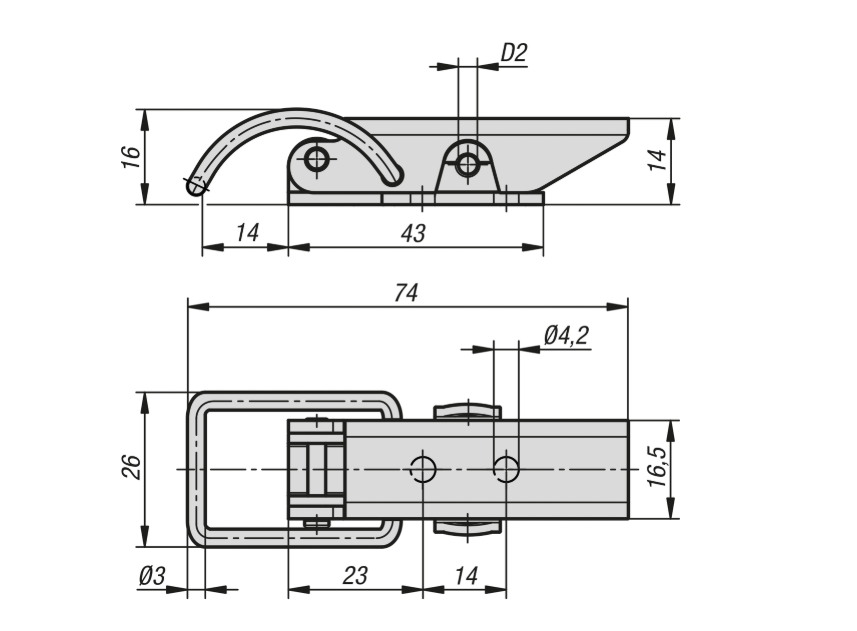
| Draw latch K2469 | Steel/stainless steel, round bail, up to 900 N, concealed holes. Hole spacing 14 mm, holes Ø 4.2 mm. Kipp |
| Catch K2468 (9142132) | The catch for the latch. Kipp |
| Bearing 608-2RS (8x22x7) | For example RS PRO 608-2RS, a skateboard bearing works too |
| Threaded inserts M4 and M5 | For example McMaster-Carr or CNC Kitchen inserts at 3DJake. The length of the insert must match the depth of the hole (CNC Kitchen standard: M4 8.1 mm, M5 9.5 mm) |
| Screws M4, M5, M8 and washers 8x12 and 8x16 | The numbers are with the steps and in the bill of materials |